Sprawl is full of bouncy and springy buildings. This post is about this elastic building effect.
I’ll assume some level of familiarity with writing shaders in Unity (and some calculus + linear algebra).
The springy building is essentially achieved in two parts. First, there is a vertex shader that deforms the mesh along a curve — while preserving the structure of the building. Second, there is a C# script that controls the angle of the bend via player interaction and handles the springy dynamics (using the heavy ball algorithm).
The whole effect was designed to be efficient. We can use this shader on 100 buildings simultaneously on mobile without observing a significant performance hit. Before we spill the beans, it’s time for some maths…
Preserving mesh structure
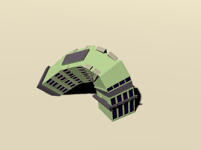
How can we deform the building while making sure it still looks like a building? In the early iterations of this effect, I didn’t put enough thought into how I wanted the bending to look at extreme angles and this led to some pretty ugly results. The version we use now looks good even with large deformations.
There are two important design choices I made for this to work. First, the building should deform so that locally its “up” frame of reference matches the curve direction. Second, while the volume of the building changes, the area of each cross-section should remain the same.
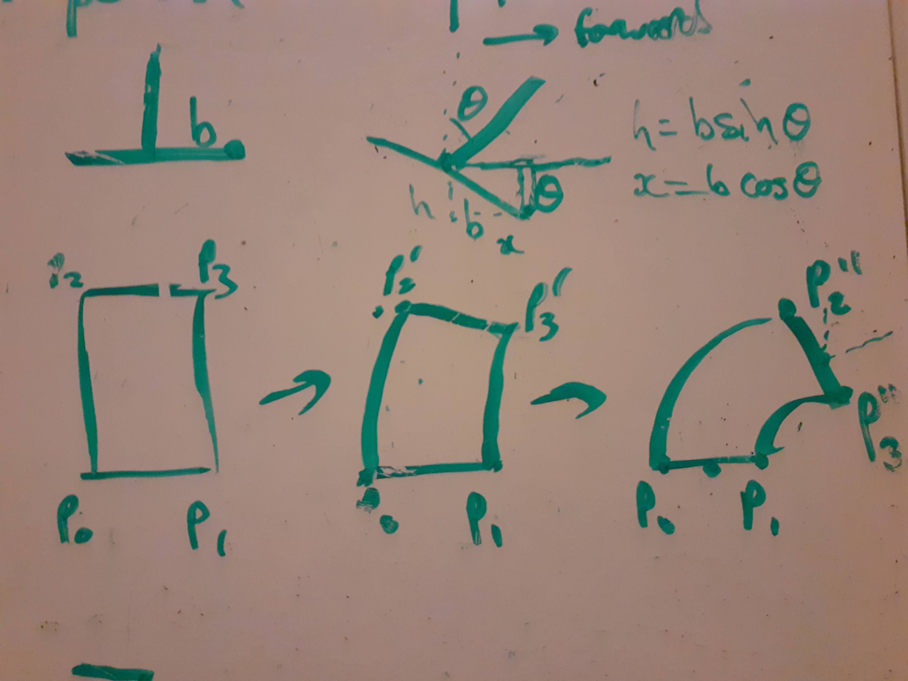
Some whiteboarding helped me figure out what I wanted the mesh to do.
- Each horizontal cross-section has its area preserved.
- Each vertex finds a point on the curve using only its height
- We rotate all vertices about the local frame defined by the curve tangent at their height
- We want the bottom of the mesh to remain fixed and parallel to the floor.
- The curve should start at the bottom of the mesh
- The tangent to the curve should point directly up at the start
- We don’t want the mesh to self-intersect
Background — Bezier curves
Our deformation uses Bezier curves, which can be thought of as a generalization of linear interpolation. This isn’t the only curve that would work, but it has some nice properties that will be important later.
We’ll focus on just one member of the Bezier curve family, the Quadratic Bezier Curve. These curves utilize three points, \(P_1, P_2, P_3\), and can be evaluated at a point \(t \in [0, 1]\) by the following formula,
\[y = (1 - t)^2 P_1 + 2(1-t)t P_2 + t^2 P_3.\]
We will also want to compute the tangent to the curve, that can be derived as,
\[\frac{dy}{dt} = 2 \left[(1 - t)(P_2 - P_1) + t(P_3 - P_2)\right].\]
Code
using UnityEngine;

public static class QuadraticBezier
{
    /// Evaluate the quadratic Bezier curve
    public static Vector3 GetPoint(Vector3 p1, Vector3 p2, Vector3 p3, float t)
    {
        float r = 1f - t;
        return r * r * p1 + 2f * r * t * p2 + t * t * p3;
    }

    /// Evaluate the derivative of the quadratic Bezier curve
    public static Vector3 GetDerivative(Vector3 p1, Vector3 p2, Vector3 p3, float t)
    {
        return 2f * ((1f - t) * (p2 - p1) + t * (p3 - p2));
    }
}
Note that the tangent is given by linearly interpolating between the vectors \(P_2 - P_1\) and \(P_3 - P_2\). So by choosing \(P_2\) to be directly above \(P_1\), we can guarantee that the curve tangent points directly up at the base of the building!
We can also reduce unwanted self-intersections by choosing \(P_2\) to be smaller than the height of the building.
Local frames along the curve
A local frame refers to the orientation of an object in some small region of space. In this case, we mean the orientation of each horizontal slice of the building.
We can compute the local frame by taking the tangent at point \(t\), and computing the rotation required to move the up direction towards the tangent.
Code
In C#, the rotation defining the local frame can be computed as a Quaternion.Vector3 tangent = QuadraticBezier.GetDerivative(P1, P2, P3, t);
Quaternion rotation = Quaternion.FromToRotation(Vector3.up, tangent);In our shader, we’ll use a slightly different approach to achieve the same effect.
There is one more thing we need to determine before we can use our Bezier curves. Where do we place the points?
Building our Bezier curves
We’ve already pointed out that we should place \(P_1\) at the base of the building, and \(P_2\) should be directly above \(P_1\) (but below the top of the building) to ensure the base isn’t rotated off the ground. What about \(P_3\)?
The final point in our Bezier curve is determined with a direction and angle. We’ll place \(P_3\) on a hemisphere with a radius equal to the building height — the angle will determine how close the building is to the equator of the hemisphere, and the direction will determine which way it points outwards.
This approach guarantees that when the angle is zero, the building retains its original form. As the angle increases, the building is deformed more until the top of the building is touching the floor. Additionally, by choosing \(P_2\) to be closer to the top of the building, we get a larger arc, and closer to the floor gives a flatter curve.
Finally, we’re ready to start writing our shader.
Writing the shader
We’ll write a surface shader with a custom vertex program that deforms the mesh. Our deformation will work in object space and will make some assumptions about the mesh that we’re deforming — namely, that its origin is at the base of the mesh and that we want to bend around the up-axis.
Implementation
First, we will rewrite our Bezier curve functions in a new file, Bezier.cginc.
Bezier.cginc
// Evaluate quadratic Bezier curve
float3 QuadBezier(float3 a, float3 b, float3 c, float t)
{
    float r = 1 - t;
    return r * r * a + 2 * r * t * b + t * t * c;
}

/// Evaluate the derivative of the quadratic Bezier curve
float3 QuadBezierTangent(float3 a, float3 b, float3 c, float t)
{
    return 2 * ((1 - t) * (b - a) + t * (c - b));
}
Setting up the shader
For this post, we’re using Unity 2019.4.8f1. Let’s begin by creating a new surface shader in unity. As a first step, we’ll add the properties that we’ll need to the property block.
Properties
{
    _Color ("Color", Color) = (1,1,1,1)
    _MainTex ("Albedo (RGB)", 2D) = "white" {}
    _Glossiness ("Smoothness", Range(0,1)) = 0.5
    _Metallic ("Metallic", Range(0,1)) = 0.0
    // Our custom properties
    _CurveAmount("Curve Amount", Range(0,1)) = 0.5
    _Angle("Angle", Range(-90, 90)) = 0
    _CurveDir("Curve Dir", Vector) = (0, 1, 0, 0)
    _MeshData("Mesh Data", Vector) = (0,0,0,1)
}
There’s a few custom properties here. _CurveAmount will determine the height of \(P_2\) as a fraction of the height of the mesh. Both _Angle and _CurveDir will be used to determine \(P_3\) as described above. This leaves _MeshData, that will contain the origin of the mesh (in the xyz coordinates) and the height of the mesh (in the w coordinate). We’ll fill _MeshData manually for now, but in Sprawl these values are computed and fed to the shader via a C# script. Actually, these properties are part of a Material Property Block, so that each building instance can be controlled uniquely.
Now we’ll modify our surface shader to use a new custom vertex program.
// Inside the surface shader subprogram
#pragma surface surf Standard vertex:vert // <- Note the added vertex directive
#pragma target 3.0

#include "Bezier.cginc"

float _CurveAmount;
float _Angle;
float3 _CurveDir;
float4 _MeshData;

void vert (inout appdata_full v) {
}

//... surf program under here
We’re now ready to start writing our vertex program.
Computing the Bezier curve
The first step we’ll take is computing \(P_1\), \(P_2\), and \(P_3\). To do this, we’ll need to use the mesh data — which tells us where the base of the mesh is and its height.
void vert (inout appdata_full v) {
    const float Deg2Rad = UNITY_PI / 180.0;

    // Get the mesh data
    float3 meshBase = _MeshData.xyz; // <- P1
    float meshHeight = _MeshData.w;
    float3 meshUp = float3(0, 0, meshHeight);
    float3 meshTop = meshBase + meshUp;

    // Compute curve data
    float3 curveDir = normalize(_CurveDir.xyz);
    float3 curveTarget = meshBase + meshUp * _CurveAmount; // <- P2
    float3 curveEnd = curve_end(meshBase, curveDir, meshHeight, _Angle * Deg2Rad); // <- P3
}
We used a function here that we haven’t defined yet, curve_end. This function computes \(P_3\), as follows,
float3 curve_end(float3 base, float3 dir, float height, float angle)
{
    return base + height * (sin(angle) * dir + cos(angle) * float3(0,0,1));
}
Updating the vertex position
Now that we have the points of our Bezier curve, we need to compute the updated positions of the vertices. The offset for the vertices is given by evaluating the Bezier curve at the vertex height (normalized).
void vert (inout appdata_full v) {
    // Get the mesh data
    // ...

    // Compute curve data
    // ...

    // Compute this vertex position
    float height = clamp(v.vertex.z / meshHeight, 0, 1); // Compute relative height of vertex
    float3 bPoint = QuadBezier(
        meshBase, curveTarget, curveEnd, height
    );

    // Update the vertex position
    float4 newPos = float4(v.vertex.x, v.vertex.y, 0, 1);
    newPos.xyz += bPoint - meshBase;
    v.vertex = newPos;
}
This code computes the relative offset of the vertices correctly from the Bezier curve, and updates the positions accordingly. But it doesn’t quite work, yet.
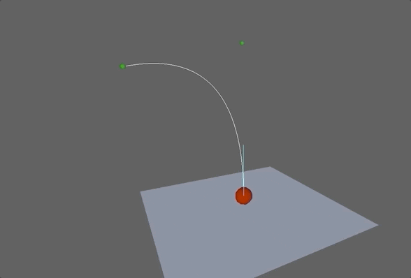
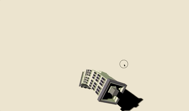
The bending looks decent for small angles, but at larger angles it is clear that the deformation is incorrect. The mesh is shearing, causing an inconsistent structure. And the normals aren’t being updated, causing incorrect lighting.
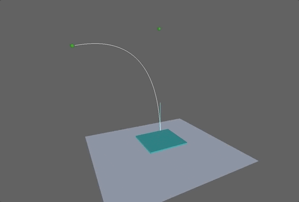
To fix these issues, we need to update the local frame for the vertices, depending on their height.
Rotating the local frames
To achieve the desired deformation, we will rotate all vertices at height \(z\) about the point \((0,0,z)\) according to the curve’s tangent direction.
void vert (inout appdata_full v) {
    // ...
    float3 bPoint = QuadBezier(
        meshBase, curveTarget, curveEnd, height
    );
    // Compute the tangent too
    float3 bTangent = QuadBezierTangent(
        meshBase, curveTarget, curveEnd, height
    );

    // Compute the rotation axis
    float3 rotAxis = cross(curveDir, float3(0, 0, sign(_Angle)));
    // Some trigonometry to get the cosine of the rotation angle
    float cosAngle = bTangent.z / length(bTangent);
    // We use Rodrigues' rotation formula
    float3 rotOffset = rodr_rot(rotAxis, cosAngle, float3(v.vertex.x, v.vertex.y, 0));

    // Update the vertex position
    float4 newPos = float4(rotOffset, 0, 1);
    newPos.xyz += bPoint - meshBase;
    v.vertex = newPos;
}
Rodrigues' rotation formula
Rodrigues' rotation formula is used to apply a 3D rotation to a vector. It needs some rotation axis (k), an angle, and a vector to be rotated (v).
float3 rodr_rot(float3 k, float cosangle, float3 v)
{
    // We work with the cosine directly, instead of doing a costly arccosine before
    float sinangle = sqrt(1 - cosangle * cosangle);
    return cosangle * v + sinangle * cross(k, v) + dot(k, v) * (1 - cosangle) * k;
}
The rotation code here is quite dense. We first compute rotAxis, the axis of rotation for our local frame. This depends on the curve direction and whether we are using a negative or positive angle (hence the sign(_Angle) function).
We then compute the cosine of the angle that the tangent makes with the global up axis. This is used to rotate the vertex offset from the mesh center-line to match the local frame from the Bezier curve. Phew!
Our building now deforms correctly!
Final touches
And finally, we’ll correct the normals and tangents.
void vert (inout appdata_full v) {
    // ...
    // Correct normals and tangents
    v.normal = rodr_rot(rotAxis, rotAngle, v.normal);
    v.tangent.xyz = rodr_rot(rotAxis, rotAngle, v.tangent.xyz);
}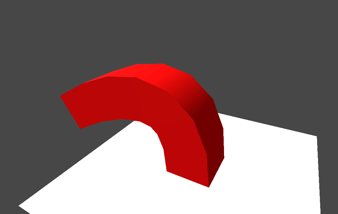
Our shader is now complete! We can deform the building, in any direction, and control the amount of deformation via the _CurveAmount property. The building retains its structure and the normals and tangents are updated to match the deformation.
Full vertex program
float4 _MeshData;
float _Angle;
float _CurveAmount;
float3 _CurveDir;

float3 curve_end(float3 base, float3 dir, float height, float angle)
{
    return base + height * (sin(angle) * dir + cos(angle) * float3(0,0,1));
}

float3 rodr_rot(float3 k, float cosangle, float3 v)
{
    float sinangle = sqrt(1 - cosangle * cosangle);
    return cosangle * v + sinangle * cross(k, v) + dot(k, v) * (1 - cosangle) * k;
}

void vert (inout appdata_full v) {
    const float Deg2Rad = UNITY_PI / 180.0;

    // Compute curve data
    float3 meshBase = _MeshData.xyz;
    float meshHeight = _MeshData.w;
    float3 meshUp = float3(0, 0, meshHeight);
    float3 meshTop = meshBase + meshUp;
    float3 curveDir = normalize(_CurveDir.xyz);
    float3 curveTarget = meshBase + meshUp * _CurveAmount;
    float3 curveEnd = curve_end(meshBase, curveDir, meshHeight, _Angle * Deg2Rad);

    // Compute this vertex position and Bezier tangent
    float height = clamp(v.vertex.z / meshHeight, 0, 1); // Compute relative height of vertex
    float3 bPoint = QuadBezier(
        meshBase, curveTarget, curveEnd, height
    );

    float3 bTangent = QuadBezierTangent(
        meshBase, curveTarget, curveEnd, height
    );

    float3 rotAxis = cross(curveDir, float3(0, 0, -sign(_Angle)));
    float cosAngle = bTangent.z / length(bTangent);
    float3 rotOffset = rodr_rot(rotAxis, cosAngle, float3(v.vertex.x, v.vertex.y, 0));

    // Update the vertex position
    float4 newPos = float4(rotOffset, 1);
    newPos.xyz += bPoint - meshBase;
    v.vertex = newPos;

    // Correct normals and tangents
    v.normal = v.normal = rodr_rot(rotAxis, cosAngle, v.normal);
    v.tangent.xyz = rodr_rot(rotAxis, cosAngle, v.tangent.xyz);
}
Before we move on to the spring effect, lets discuss a few caveats with this approach.
Some caveats
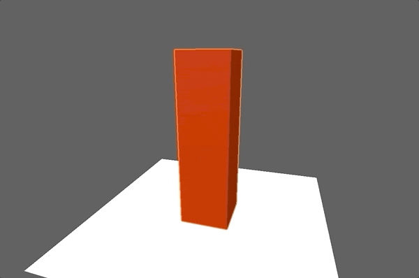
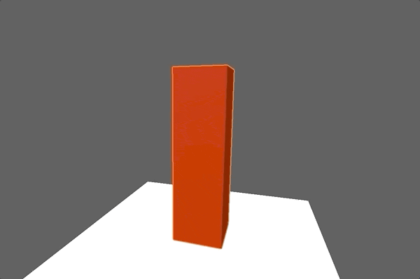
The attentive readers among you might have noticed that, unlike our Sprawl building, our red block has no shadow. If we enabled shadows, we would see that the shadows do no match the deformed mesh. I left this out as this post was already very long, but there’s nothing significantly difficult for shadows. We just need to update our shadow vertex program to match the deformed mesh.
This shader isn’t a realistic model of elastic deformation, just one that looks good. There are many approaches to getting more realistic deformations — my favourite for interactive applications is via Position Based Dynamics. We implemented a simple version of this in Unity not too long ago!
Having fun with deformable meshes (thanks @catlikecoding for the tutorials!) and interactive physics via position based dynamics.#gamedev #indiedev pic.twitter.com/j5FoWOSRWR
— GlassTomeGames (@GlassTomeGames) May 26, 2020
Springs, or a heavy ball?
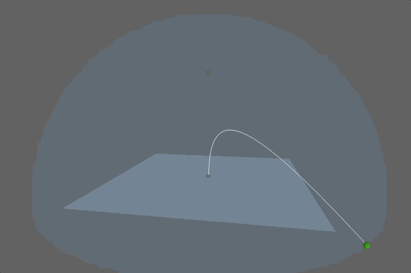
The elastic pinging effect shown at the top of this post is produced using on of my favourite algorithms — the heavy ball algorithm.
The heavy ball algorithm is used for optimization. Given some function (and its gradients), it searches for the minimum of that function. The name comes from some intuition for the algorithm — it’s like placing a heavy ball at some point on the function’s surface, and letting it roll down towards the lowest point.
Explaining the full algorithm is out-of-scope for this post, but I’ll present the updates the algorithm gives for our use case. We’ll begin by creating a new class, that we can query to apply a step of the heavy ball algorithm.
public class HeavyBall1D
{
    float parameter = 0f; // The parameter we're updating
    float momentum = 0f; // Momentum buffer
    float speed; // Speed of the algorithm
    float damping; // Damping factor of the algorithm

    public HeavyBall1D(float speed, float damping)
    {
        this.damping = damping;
        this.speed = speed;
    }

    /// Reset the algorithm to this parameter
    public void Reset(float parameter)
    {
        this.parameter = parameter;
        this.momentum = 0f;
    }

    public void Step(float deltaTime)
    {
        // ...
    }
}
The step function first updates the momentum buffer, with some damping so that a little momentum is lost with each update. And then uses the momentum to update the current parameter.
public void Step(float deltaTime)
{
    // Update the momentum buffer
    momentum = damping * momentum + parameter;
    parameter -= deltaTime * speed * momentum;
}
This update will push the parameter towards zero. If the damping coefficient is set high enough (but less than 1), then the parameter will overshoot zero and spring back until it eventually converges.
Additional notes on heavy ball
The heavy ball algorithm finds the minimum of a function, f. More generally, the update can be written as follows.
public void Step(float deltaTime)
{
    // Update the momentum buffer
    momentum = damping * momentum + gradf(parameter);
    parameter -= deltaTime * speed * momentum;
}
Where gradf returns the gradient of f evaluated at the current parameter.
Here, I’m using a 1D quadratic function whose minimum is at zero, \(f(x) = 0.5 x^2.\) We can easily push the parameter towards non-zero values by modifying the function: \(f(x) = 0.5(x - a)^2\).
We can use any function with this algorithm. Nowadays, I most often use this algorithm to update the weights of a neural network. I was surprised and happy to see how well it can work visually like this.
So how does it look?
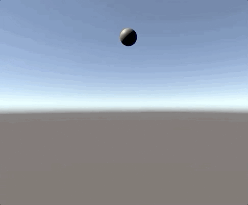
Testing out the heavy ball algorithm on a heavy ball. Here we use the algorithm to update the y-position of a sphere.
Code
public class SpringyBall : MonoBehaviour
{
    public float damping = 0.8f;
    public float speed = 4f;
    HeavyBall1D heavyBall;

    public bool hbActive = true;

    void Awake()
    {
        heavyBall = new HeavyBall1D(speed, damping);
        heavyBall.Reset(transform.localPosition.y);
    }

    void FixedUpdate()
    {
        if (hbActive) {
            Vector3 pos = transform.localPosition;
            pos.y = heavyBall.Step(Time.deltaTime);
            transform.localPosition = pos;
        }
    }
}
The heavy ball algorithm will serve as the foundation for our dynamic springiness. All that’s left is to add some interaction, as everything is more fun when you’re the one doing it.
Adding interaction
At this point, the post is getting pretty long and we’ve covered the most exciting parts. So I’ll give the broad strokes for the interactive elements here, which are nothing special.
- First, detect when the building is clicked
- Until the mouse is released,
- We raycast to find the position of the mouse on a horizontal plane at the building’s base
- We set the curve direction shader property to match this position relative to the building
- We set the angle to be proportional to the mouse distance
- When the mouse button is released, we rely on heavy ball to pull the angle back towards zero
Usage in Sprawl
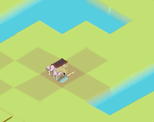
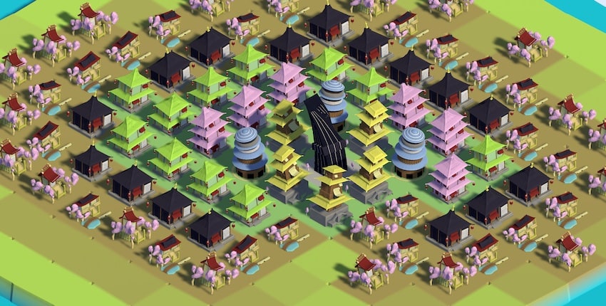
We introduced this shader to Sprawl a couple of weeks ago, and really like how it fits.
We use this heavy-ball spring effect to make moving buildings around feel really fun. As you drag the buildings, they tilt in the direction of the movement. When you release the buildings, they pop into their new position and spring back and forth a little.
Not everything went as planned though.
We had a bug that made all of our buildings slightly bendy when they spawned. We liked how it looked, so now it’s a feature.
Sprawl has come a long way since we slapped it together for the GMTK 2020 jam. We’ve been hard at work improving the controls, UI, performance, and basically everything else. Keep an eye on this blog for more updates as we edge closer to release and complete our email form so that we can let you know when the game releases, for free, on mobile soon!